Sunday, 10 December 2023

 Wow it has been a long time, so long that I forgot to upload my 2018 update. Which has now been uploaded as is. 

No work has been done on the layout planning. 

I have spent most of my time playing the transport simulation game Transport Fever 2


Friday, 22 April 2022

Still Planning - 2018 post

It has been a while, I am still planning.

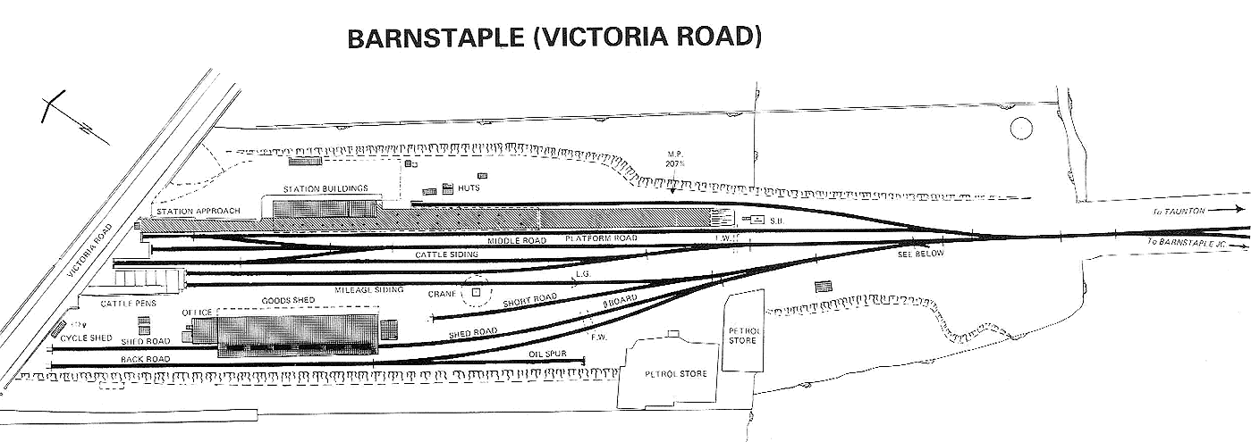
I have been looking into to stations I could model, currently I am thinking of using Barnstaple (Victoria Road) station as a template for my branch line terminus station.

Anyhow here are the stations that I am interested in:


Currently I have chosen Barnstaple (Victoria Road) as the template for a Branch-line terminus as it has:

  • Engine shed (2 road) 
  • Turntable
  • Station has two platforms 
    • main platform has a runaround shared with cattle siding
  • Goods shed with runaround (rack road) and an oil spur.
  • Cattle siding that shares the runaround with the main platform.
Track layout as per greater western.


Saturday, 4 March 2017

Blog entries that were drafts since 2015


Going over my blog entries, I had found three drafts from 2015, that I have decided to release as part of this entry. I am still working on creating a viable plan which keeps on proving difficult as I attempt to include heritage and main line stock operations. One idea from this a station that has both Mainline and Heritage facilities,  which will in a future post.

Anyhow as previously mentioned listed below are blog entries that I have had in draft since 2015.

April 4th 2015

I am still stuck on the design phase of my layout plan, as I have realised that it would be a good idea for the terminus station to be transformed into a through station when required. Which then links in with the station's history of it originally being a through station. I have also been trying to shrink the size of this facility. The biggest hurdle to this is supporting a full length HST of two power cars and seven coaches with an estimated length of 1.42 metres. As the station platforms, a head shunt  and stabling will need to fit a full length HST. The stabling is in parallel to the head shunt and can access the station platforms. If I do it this way I can have a single road full length HST servicing facility parallel to the station platforms. All of which leads to at least 3.50 metres for the length of board required to make it.

Terminus Station - Version 8.17 (Scrapped Idea) 5.8 metres long
Terminus Station - Version 10.00 (incomplete)
Version 10 of my plan is very much in the draft phase. The idea is platforms 1 and 2 are for short trains such as DMUs of three coaches or a steam locomotive with a rake of two coaches in a push-pull configuration. Platform 1 can support two three car DMUs due to the double crossover, which gives us platforms 1a and 1b. Platforms 3 and 4 are through platforms, and can support a steam locomotive (155 mm) and a rake of nine Mk1 coaches (136 mm * 9).

I will have a more accurate measurement once I receive my pre-order of the Dapol HST intercity swallow livery bookend set.

18th March 2015

This is the original terminus idea I had, unfortunately it takes up too much space. If I had the space this is the plan I would use.

Essentially the maintenance facilities with the HST/DMU stabling are to the left of the station. Whilst the coach stabling and HST/DMU servicing facility are parallel to the station platforms. Locomotive storage is parallel to platform one, where a station canopy has been erected to protect them from the elements. Although I am thinking this may be best for diesel locomotives and visiting steam locomotives. For the permanent steam locomotives a round house is in use.

Below is a list of tractive equipment I either have or plan to own and use on my layouts:


  1. Steam Locomotives
    • Princess Coronation Class:
      • Duchess of Norfolk (BR Express Passenger Blue, Early Crest)
      • City of Coventry (BR Crimson, Late Crest)
    • Ivatt Class
      • 2MT 2-6-0 (BR Black Lined Early Crest)
      • 2MT 2-6-0(BR Green Late Crest) wish listed }
      • 2MT 2-6-2T (BR Black Early Crest)
    • Class 3F 0-6-0 Jinty (BR Black Early Crest) wish listed }
    • Class A1 Tornado 4-6-2 (BR Brunswick Green Early Crest)
    • Midland Class 4F (BR Black Early Crest)  wish listed }
    • Fairburn Tank 2-6-4T (BR Black Early Crest)  wish listed }
    • BR Standard Class 
      • 3MT 2-6-2T (BR Black Late Crest)  wish listed }
      • 4MT 2-6-4T (BR Black Early Crest)  wish listed }
      • 4MT 2-6-0 (BR Black Late Crest) wish listed }
      • 5MT 4-6-0 (BR Black Early Emblem) wish listed }
  2. Diesel Locomotives
    • Class 08 
      • (BR Black Early Crest)
      • (BR Blue Wasp Stripes) wish listed }
    • Class 20 (BR Blue Indicator Disc) wish listed }
  3. DMU/HST
    • Class 43 HST (BR Intercity Swallow)
    • Class 43 HST (BR Intercity 125 Blue & Grey) wish listed }
    • Class 101 - 3 car (BR Blue & Grey) wish listed }
    • 2 x Class 121 - 1 car (BR Blue) 
    • Class 122 - 1 car (BR Blue)
Based on the above list, most of my motive power is steam, I may need to order a lot more coaches than I originally thought. Plus the steam facility will need to be the most important part due to the amount of steam motive power available. Luckily diesel support is not as massive as steam.


18th January 2015

I still plan to implement a DCC controller initially using the Arduino, but this is no longer urgent as I now have a SPROG 2 that I can use to control my locomotives with.

Having said that, here is a list of equipment I will use to test the dcc controller:

My vision is to use a Raspberry-Pi as train layout controller, but in order to this it will require:

  • running software like JMRI
  • expansion board that generates the dcc signal that can provide 3 - 5 amps of power, and supports the railcom cutout signal.
  • communications bus (openLCB or CMRI), allow the use of nodes to communicate ie railcom detectors.

Friday, 18 November 2016

DCC Controller- Update


I  haven't touched this project in a long time. However I have found a project that is up and running which uses the Arduino Uno/Mega to generate the DCC signal and also uses a L298 Motor Shield to act as a booster for the DCC signal. This project is DCC++ and listed below are some useful links for it:

Also there are two Raspberry Pi SPROG modules:
  • Pi-SPROG One
  • Pi-SPROG Nano
More information can be found at the Pi-SPROG webpage.


Sunday, 23 October 2016

Been a while

It ha been a while, work has been taking up the vast majority of my time. Plus I have been attempting to plan a branch lines station, which has been taking forever as I could not make up my mind, and I still can't make up my mind.

There are a few branch line stations I have been thinking of use for inspiration of my design. The stations are:

  • Arley Station on the Severn Valley Railway
  • Bodmin General
  • Goathland station

Arley Station 

I watched a YouTube video (shown below) about Arley station on the Severn Valley Railway, which made me realise that Arley station could be  good station to base a branch line station off of.


Which then lead me to watching the YouTube video D8059 Arley, 04/10/15 shunting the yard.


 The difficult part was looking for track plans, thus I used google maps to help me.

Arley Station as per Google Maps

And then I found "A drawing of the signal box track layout for Arley box at c1960, from the collection of John Hinson" located at www.signalbox.com.

Thus I decided to use Arley as the basis of my branch line station plan. Shown below are some initial track plans for the branch line station which is a work in progress.

Version zero - A basic rendition of the Arley station track plan using straight track segments

Version 007 - Extra sidings and a third platform added
Version 008 - double slip switch added
Version 012 - Station can now have double track approach on either end if required.

I still have a lot of work to do with the plan, especially as I want to give various options for the station:
  • Through station with:
    • single track access on both sides
    • double track access on one side and single track access on the other
  • Terminus station that has the terminating sides track buffer stopped and used as the head shunt. The remainder of the disused track will be populated with overgrowth. The station approach is via:
    • single track access
    • double track access
Version 012 of the track plan can now support double track on both ends of the station if required, and also follows the British goods yard access standards from when facing point locks were not in use.

As mentioned earlier Arley station is one of three candidates for my branch station idea, I also like Bodmin General and Goathland stations. 

Friday, 3 July 2015

Lack of Update

I have started working in April and I have been busy since. The plus side is the increase in funds I can use on the Model railway.

Currently I am collecting Intercity liveried coaches and locomotives, unfortunately Graham Farish and Dapol have no Intercity branded locomotives, unless one looks for second hand. I am still collecting steam era locomotives and coaches, but I also want to run some more modern coaches and locomotives on my heritage rail. Of which I am still in the design phase, I keep on getting interesting ideas that start off good, but then take up too much room.

Anyhow a list of my recent purchases:

Locomotives:
  • Class 86 Bo-Bo Electric 86415 Triple Grey 'Distribution Sector'
  • Class 5700 Pannier 0-6-0 4 in BR black with early crest
Coaches Locomotive Hauled:
  • Mk3 - 1st class Intercity Executive ( x2)
  • Mk3 - Buffet Intercity Swallow
  • Mk3 - 1st class Intercity Swallow
  • Mk3 - 2nd class Intercity Swallow (x3)
Wagons:
  • 20t EX-LMS Brake Van BR Grey
  • Conflats BR Bauxite with AF containers BR light blue (triple pack)
and I have on order:
  • Class 43 HST Book Set in Intercity Swallow
  • Mk3 TGS Intercity Swallow (x2, HST)
  • Class 3F Fowler Jinty 0-6-0 tank in BR black with early emblem
  • BR Mk1 57ft Suburban Second Open in crimson (x2)
  • BR Mk1 57ft Suburban Brake End in crimson (x2)

In regards to the HST, it is a better deal to buy the bookset than to buy the spare part unpainted motorised power car. At least with the bookset you get in addition to the motorised power car,  two coaches and dummy power car. My plan is to have a full HST rake with both power cars motorised, which means transplanting the frame from one motorised power car to a dummy power cars shell. From there I plan to have one of the dummy cars sit in my maintenance depot as apart of the scenery.

As for the suburban coaches, I have a Class 2MT Ivatt 2-6-2 tank locomotive that is push pull fitted, and thus want to convert one of the brake end coaches into a push-pull fitted driving unit. I plan to have a push pull rake of four coaches.

And of course my planning is still an ongoing journey as shown below. The biggest issue is keeping the length down to 3-4 metres.


Saturday, 4 April 2015

Latest Arrivals

I had received on Friday (20/03/2015) the Coronation class locomotive "City of Coventry" in the BR maroon livery with the late crest. Which I have not tested out, as I was waiting on my order of Kato unitrack to arrive, which happened today (24/03/2015). Andfinally I did test run the locomotive on Thursday (02/04/2015), which ran well and looks good with Maroon coaches.

City of Coventry running on Kato Unitrack
Kato Unitrack
Video footage of the locomotive going backwards as the last part of the burn in.


And just for fun, a video of  the locomotive pushing a HST standard class coach with a DVT in front.


Plus I have received some volumes of a series of books about steam depots in various BR Regions - the series is called "BR Steam Motive Power Depots" by Paul Bolger. The regions I have are:
  • North Eastern Region
  • Western Region
  • London Midland Region (second hand)

And now I am in search of books about the diesel traction motive depots (TMDs). These books should help me plan the maintenance facility for the heritage railway depot located at the main terminus.

I have received on Wednesday (01/04/2015) another Arduino UNO, which will be replacing my microduino as the train controller.

Monday, 16 March 2015

Test Track

Currently I do not have a layout and have instead been using a mixture of track to make a simple oval as my test track. Which was assembled on the dining room table, and thus a temporary set-up that was problematic to assemble (and disassemble).

So instead I will use some Kato Unitrack to form an oval, the main benefit for me is that Unitrack is designed for repeated assembly (and disassembly).


As shown in the diagram above I can have it on my computer table. If needed I can also have it on the dining room table but that requires reducing the quantity of straight sections used.


I have just ordered the required track to make the loop.


Monday, 9 March 2015

Layout Plan - idea change - Part Two

Yes there is a part two. The previous diagrams was getting the idea out of my head. Now that I have looked at it, there are a few changes I want to make. 

There are too many maintenance buildings, there are currently four buildings  that are, coach/carriage shed, steam locomotive maintenance, diesel locomotive maintenance, and HST/DMU maintenance buildings. Instead I should be able to make do with one or two buildings, one building with between 2, 3, or 4 rail access should be fine. One rail access section could be lengthened to support three car DMUs. As for the HST, it can be uncoupled and the parts (coach or power car) requiring maintenance can be shunted into the facility.

There are two separate facilities to handle steam and diesel locomotives, which are separated by the main line. Instead both facilities should be merge, allowing for the sharing of facilities and yard track. The turntable can be used for both diesel and steam locomotives, also providing them access to locomotive storage tracks. This has the impact of removing some complexity by the removal of paths into and out of the previous plans steam facility. Which allowed for the reshuffling of points and slips positions which will allow the layout to be shortened.

Currently there are two stabling areas, instead they will be merged, and the location will be where the coach stabling tracks are. The approach tracks will need to be adjusted to ensure full length HST (rake of seven coaches) will fit in the HST stabling section. The HST and DMU stabling will be as close as possible to the diesel refuelling area, and furtherest from the station platforms.

The bay platforms (platforms 1 and 2) will stay as they have little impact on the positioning of points and slips, plus I like the idea a bay platform.

There will no longer be a head shunt, instead any of the three tracks the connect to the station can be used. But the default track to use is the third line - which is bidirectional and terminates by linking back into the two line mainline. This track is an alternative path to the station in case there is an issue with the approach track. 

Building up and breaking down a rake of coaches can be done within the yard.

Version 5.08 of the Terminus


Friday, 6 March 2015

Layout Plan - idea change

The last idea was really good, but I just had a different idea that may be better. The issue with the last layout is there is only one station area that can be seen and lots of hidden staging. What is needed is a second station and maybe some yard facilities. To do this I would take my branch station idea and make it an upper layer which will then be sitting on some hidden staging yard tracks, and sitting behind the main station and yard facilities (which will be on the ground level).

I do plan to take this layout to exhibitions, thus it is important that an audience can be entertained, thus the need for at least two stations. Plus it can be used to show the turnaround of passenger trains, as well as the break down and reassembly of goods trains.

I'll update this post once I have completed my layout plan in AnyRail.

Taking longer than I thought, and of course it is the allowances for the HST that is the problem - I use 1.42 metres for the station platform and I need to use that for the servicing sheds and stabling as well. I'll have the stabling and shed parallel to each other otherwise even more space is wasted. And then there is the required point work to direct locomotives, trains, and coaches to their required locations, which also requires space. So far I have a length of 4.00 metres for the layout, with my luck I will need to go to 5 metres.

I have the coach stabling parallel to the platforms to reduce wasted space.

The bottom half of the diagram below is the area I am currently working on.

Draft Plan

Updated version of the plan for the terminus and depot.
Version 4.11 of the plan
Current length is 4.25 metres, the platforms need to fit a regular sized HST with a rake of 7 coaches and two power cars. 7 * 165 mm + 2 * 125 mm = 1155 + 250 mm = 1405 mm = 1.41 metres. The plus side of this is that the station can handle a rake of 7 coaches, and allow the locomotive to escape via the run around track. Otherwise if the locomotive is trapped then a a rake of 9 coaches can fit, and an alternative locomotive will need to be used to move the train.

HST Book Sets

Just received an email from Ehattons mentioning that the Dapol HST (Class 43) Book Sets in the Blue & Grey livery, and the Intercity Executive livery are available. But no mention of the Intercity Swallow livery which I have on pre-order.

Thursday, 5 March 2015

Layout Plan - Update

I decided to adjust the plan to make the layout independent when required, but with the option to connect to other layouts. Also The under level can be used to add time to a rail journeys. Unfortunately this addition meant that the width and length had to be increased to a total of 780 mm x 3100 mm.
Ground level
Under level
A double track spiral will be used to connect both levels. The plan is nearly there, I just need to make adjustments, the current under level version was to get track out without thought.

Advantages:
  • Lower level can be used as test track, as it has the loop implemented.
  • Layout can operate on it's own
  • Layout can operate with other layouts
  • Storage cassette loading/unloading of locomotives and rolling stock
  • Full size HST (rake of seven coaches and the two power cars) will fit on the stations main platform. (Based on estimated lengths).
  • Only one double slip used on ground level, due to space restrictions. (might be able to remove it)
Disadvantages:
  • Complexity - needs to be gone over to adjust track work
  • Spiral - will my locomotives be able to handle it under load.
  • Increased layout board size - 
    • width increased by 430 mm
    • length increased by 600 mm
  • Electrical complexity
    • Wye
    • Reversing loops
  • Building the storage cassettes 
  • Cost of points and double slips.

Wednesday, 4 March 2015

Part Way to an N gauge HST

I am part way to an n gauge HST in the Intercity Swallow livery. That is I have purchased three Dapol coaches that are TF, TRSB, and TS.

TF, TRSB, and TS
To complete it I am now waiting on Dapol to release the TGS, a renumbered TS and the HST bookset. The bookset is composed of two DMB, a TF, and a TS.

The fun part with the HST is that formations could be changed, I plan to mainly use the formation DMB-TGS-TS-TS-TS-TRSB-TF-TF-DMB. But I do plan to be able to mix it up a bit by having some extra coaches such as:

  • 1 extra TRSB
  • 2 extra TS
  • 1 extra TF
Which can be stabled at my planned major station layout module of my heritage line. Which will be a long way off, as initially I plan to build a small branch line terminating station layout module.
List of codes and their descriptions.

When I first  saw the HST in a Hornby catalogue in the late 80's, I knew I had to get one. It has been approximately 25 years since, and I plan to have one.

Wikipedia links about the HST:
http://en.wikipedia.org/wiki/British_Rail_Class_252 <-- Prototype
http://en.wikipedia.org/wiki/British_Rail_Classes_253,_254_and_255
http://en.wikipedia.org/wiki/British_Rail_Class_43_(HST)
http://en.wikipedia.org/wiki/British_Rail_Mark_3#HST_vehicles <-- Coaching Stock
http://en.wikipedia.org/wiki/InterCity_125
http://en.wikipedia.org/wiki/British_Rail_corporate_liveries
http://en.wikipedia.org/wiki/InterCity_(British_Rail)

Formations
http://www.rmweb.co.uk/community/index.php?/topic/38178-hst-formations/
http://www.rmweb.co.uk/community/index.php?/topic/18939-hst-formation/
http://www.ngaugeforum.co.uk/SMFN/index.php?topic=2452.0
http://ftp.uktrainsim.com/viewtopic.php?f=143&t=71376&p=855859

Misc links:
http://www.tauntontrains.co.uk/HST.htm

DCC Control Station

A big thank you to Malhar Deshmukh for his comment which helped remind me that I was going to work on the Arduino as a command station.

Unfortunately before now, I was sidetracked by other things such as my layout planning (and it's multiple revisions and restarts), as well as my growing collection of locomotives and coaches.

My original plan was to use an Arduino Uno as a simple dcc control station that can control a few dcc locomotives and devices. In order to do this I will need to make use of:
  • an Arduino Uno (or Arduino compatible)
  • an LCD (I2C interface)
  • a few buttons and LEDs
  • a key pad
  • the software CmdArduino (created by D.E. Goodman-Wilson)
  • a dcc booster (as I am too lazy to build a h-bridge)

As for test equipment, I will be using:

The code for this will be hosted on GitHub and is a fork of the CmdArduino repository which is also hosted on GitHub. The fork of CmdArduino I have made is located at:  https://github.com/dtcole/CmdrArduino


Initial Plan


  1. Setup the code to have the potentiometer set the speed in one direction and instead use two buttons to control the direction.
  2. Attach I2C LCD and insert support code to run it. 
    • Modify CmdStation.ino to display loco information (address, speed, and direction).
  3. Attach keypad, and modify CmdStation.ino to support it, 
    • insert test code to verify keys pressed match what the arduino sees.
  4. Create a menu that allows:
    • the user to add and remove a locomotive (DCC Address, and name). 
    • select a locomotive by name for direct control.  
    • the # button to return to the main menu.
    • the * button to return to the currently selected locomotives information 
I will create a new post once I have the above mentioned working.

Thursday, 12 February 2015

Raspberry Pi 2

Today I received the Raspberry Pi 2 Model B, that I had ordered two days ago.


The Pi will be used to control the SPROG IIv3 by running JMRI. Luckily the latest NOOBS (1.3.12) has the java runtime environment 1.8.0-b132 installed, so I only had to download the latest JMRI production version (3.10.1) for Linux.

JMRI DecoderPro3 running on the Raspberry Pi
Using Putty and Xming on windows to access the Raspberry Pi and run DecoderPro3

Hardware used:
  • Raspberry Pi 2 Model B
  • USB Wifi Adapter
  • SPROG IIv3 with USB lead.
  • Mobile phone (Samsung Galaxy S4) charger and USB lead, as it is already plugged in. Otherwise any USB power supply that can provide 1 amp or higher with a micro USB connector.
Software Used:

Update

I just tried the Pi out with my SPROG via JMRI which had a communications issue which was solved by reading the JMRI users group. The issue is the pi does not like the JMRI armv71 library, the solution is to overwrite it with the armv61 library. The thread to read on the JMRI users group is Raspberry Pi 2 model B - help please.

$ pwd 
/home/pi
$ cd JMRI/lib/linux
$ pwd
/home/pi/JMRI/lib/linux
$ sudo tar -zcvf armv7l.orig.tar.gz armv7l
$ sudo cp -v armv6l/* armv7l/

SPROG IIv3 and Raspberry Pi 2 Model B connected together via USB

Layout planning update

After some consultation with other modellers on the N gauge forums, I have come to the realisation that I should model a heritage railway line. As this will allow me to use equipment from various periods of UK rail history. Like the Dapol HST (Class 43 in Intercity Swallow livery) that I have on order.

I am currently figuring out a history for my heritage line, listed below is a draft of my ideas for the history:
  • It was originally a branch line linking two main lines, and had a junction for another branch line that terminated at a rural community.
  • Was closed down due to the Beeching cuts.
  • Not all of it could be saved, as local governments wanted the land for development purposes.
  • Thus the main facilities and terminus used to be a through station and junction:
    • The junction still exists and so does the branch line that ends at a small rural community.
    • The other part continues onto one of the main lines.
    • The other mainline link is gone, thus the terminus station.

Currently I have three stations to choose from to model, I have listed below a draft of my vision of the three stations:
  • Branch branch line terminus
    • Rural station
    • 1 main platform (4 ~ 6 coaches) with a bay platform (3 coach DMU)
    • turntable to turn locomotives around (including diesel)
    • one or two through sidings - runaround and freight breakdown.
    • small goods shed and cattle dock
  • Branch line terminus (previously a through station)
    • Previously the through station.
    • Three platforms that can handle rakes of 6 coaches
    • One bay platform that can support a DMU of 3 coaches or a steam push pull train consisting of a tank engine and a rake of two coaches.
    • With heritage rail takeover the following was facilities were implemented:
      • coach and locomotive depots
      • steam and diesel refueling facilities
      • DMU stabling yard (including fueling)
      • Automatic carriage cleaner
      • Carriage stabling yard
      • Locomotive storage
      • turntable for turning locomotives around to face correct direction.
      • small freight handling area
      • Food preparation facility and loading bay for kitchen/buffet cars.
  • Branch line meets mainline station
    • one island platform under network rail
    • heritage rail control:
      • one island platform plus two bays in middle of platform which are heritage rail.
      • or one platform plus bay platform, and then one half of a island platform, the other half under network rail control.
      • locomotive water supply at both ends.
      • colour light signals, as track on southern end joins back into the national railway (network rail).
      • In order for points to be set for the heritage rail to access the main line. Network rail via their control system needs to authorise local control of points (station signal box). Once movement is done, the signal box is required to return control to network rail. Network rail can override this but only in a safe manner. (If a train is already occupying the block or is on the points, then the points can't be changed).
      • Track heading south is by default set to head shunt. Alternate path is onto network rail.
      • There is a turntable access via head shunt.
      • There is a draft plan from network rail, to allow heritage rail northbound from platforms access to network rail northbound track. This is to facilitate northbound network rail steam trains, and emergency usage of extra platforms for non electrified equipment.
Of the three ideas, the branch branch line terminus appears to be the easiest, and will most likely to be my first construction project.

Draft plan of the Branch branch line terminus.
Based on measurements from the draft plan shown above, I should be able to fit a HST with a rake of 7 coaches easily on the main platform. Alternately I can fit a rake of 6 coaches for a regular locomotive hauled passenger train. The bay platform can handle a DMU rake of 3 coaches or a push pull fitted passenger train of 1 locomotive and a rake of 2 coaches.


Friday, 16 January 2015

Various Bits and Pieces


  1. I have received my BitScope Micro, and it works quite well. And have now received the dual channel BNC adapter, which will allow me to use my probe. 
  2. I have received a DCC chipped class 08 shunting locomotive from CR Signals.
  3. I have received the SPROG II from DCCconcepts
  4. I have now (09/01/2015) received a Princess Coronation "Duchess of Norfolk" in BR Express Blue (GF 372-186)
I have tested my class 08 locomotive with the SPROG II and they both worked.
Class 08 shunter controlled by JMRI on mac via SPROG.

Class 08 shunter

I am glad that I had ordered the Duchess of Norfolk, she has become the pride of my fleet and will be used with my Stanier coaching stock, which currently makes a rake of three coaches:

  • LMS 50ft Full brake M31319 (GF 374-886)
  • Stanier Brake 1st Coach M5060 (GF 374-831B)
  • Stanier Brake 2nd Coach M5777 (GF 374-826B)

Duchess of Norfolk with a rake of three Stanier coaches (Full Brake, Brake 1st, & Brake 2nd)

I have to get around to ordering some Stanier corridor and vestibule coaches. I do have some BR Mk1 first and second corridor coaches, and will be using them when needed.

I now need to rethink my layout plans, as my branch line idea doesn't justify the use or sighting of a coronation class locomotive. Although it has been suggested by a member of the N Gauge Forum that I could still have the duchess run on my branch in the form of a rail tour before the branch was closed or as a Heritage railway.

I do have two ideas that I would like to implement:
  1. A small to medium sized Mainline terminus with a branch-line connection, this will allow me to have an engine maintenance facility, including a turntable and some coaching stock storage. And possibly a freight handling area. 
  2. A small to medium branch line terminus - a platform that on one side can handle a rake of three to four coaches. And a bay platform on the other that can handle a rake of two coaches plus a tank locomotive, pretty much a push & pull (/motor coach) train. And some freight handling - a goods shed, cattle dock, and couple of sidings.
An example of the branch line terminus idea.
At this point in regards to the terminus idea, I plan to work on the branch line as it should be less complex than my main line.

Saturday, 1 November 2014

Absent

I had to curtail my activities in order to finish off my graduate certificate. I now have some free time to start looking at things again.

Oscillosope


Due to the limitations of the Arduino based Oscilloscope & Logic Analyzer projects I have been looking at, I have decided to purchase a BitScope Micro Oscilloscope & Analyzer, which provides the functionality I require.

Railway Research


I have been collecting books about semaphore signalling (prototypical and modelling) and coaching stock (BR Mk1&2). As well as researching the Pull & Push services run by LMS and then BR, unfortunately there appears to be no ready to run (RTR) coaches available. 

Luckily Dapol currently supplies a RTR N Gauge steam locomotive (2S-015-002) that is Push-Pull fitted, the Ivatt 2-6-2T number 41273 in BR early crest, which unfortunately is not DCC ready. 

According to Wikipedia, RailUKGloucestershire Transport History, the Ivatt Class 2MT 2-6-2T number 41273 was push-pull fitted. Gloucestershire Transport History and Goods & Not So Goods provide suggestions on how to model a generic driving van trailer for push-pull operation using the Graham Farish BR Mk1 57ft Suburban Brake End (374-312B).

Alternately Etched Pixels offers LMS suburban coach kits:

  • UMCL1022:    LMS 57ft non corridor third, pre-printed LMS sides
  • UMCL1023:    LMS 57ft non corridor brake third, pre-printed LMS sides
  • UMCL1023B: LMS 57ft non corridor brake third driving trailer, pre-printed LMS sides
  • UMCL1024:    LMS 57ft non corridor composite, pre-printed LMS sides
  • UM616:           LMS suburban trailer end (driver) (pack of two)

  • Looks like I could do it to the BR Livery for suburban passenger as well:
  • UMCC1023:    LMS 57ft non corridor brake third in BR crimson livery
  • UMCC1024:    LMS 57ft non corridor composite in BR crimson livery

  • I would need to use UM616 to convert UMCC1023 into a driving trailer of a push-pull set, but it is doable.


    Sunday, 27 July 2014

    Modifying DCC-Monitor

    I have been rather slack lately, but have been thinking about what I want to modify in dcc-monitor.

    Currently it sends the binary data down as character for each bit, thus [11111111] is actually 8 bytes of data when we could use one byte to represent it, in this case [ÿ]. From there I have added a start [H] and end [E] character and a count of characters (bytes) used for the data payload.

    Thus we could have:

    • [H2DDE] for two bytes of data.
    • [H6DDDDDDE] for six bytes of data.
    Thus the idle packet looks like [H3ÿ ÿE], where [ÿ] is equivalent to [11111111], and [ ] is equivalent to [00000000], also [ÿ ÿ] is our 3 bytes of characters.

    Now that I have dcc-monitor sending what I require over the serial link, I can now focus on creating a C/C++ program to read the serial link and display in English and Hexadecimal what the dcc packets are.

    Wednesday, 16 July 2014

    RAILbooster

    I have recieved my Railstars RAILbooster in the post today.


    It works - currently outputs 14.3VDC from supplied 15VDC, I used a bridge rectifier to enable multimeter measurement of the track voltage. (sourced the idea from dccwiki article on How to convert dcc to dc)


    Microduino sending dcc signal to booster which is being isolated in order for the arduino to monitor the dcc packet. Can't have 14.3 VDC going straight to the Arduino that would kill the arduino.

    DCC monitor in action - all those numbers (except for the idle packet - 11111111 00000000 11111111) are due to my major speed change.

    Sunday, 13 July 2014

    DCC Controller - revisted

    Before I could test out the logic analyser I had to make use of a Microduino-Core to generate the DCC signal, as I only have one Arduino Uno board. The microduino is arduino compatable and uses the ATmega328P same as the UNO.

    New Fritzing images using the Microduino, fingers crossed that the CmdrArduino files will work with it. (Updated as incorrectly connected dcc out to ground when it should goto pin 10).


    I need to do more testing of the dcc signal to see if CmdrArduino is running correctly on the microduino.

    Logic Analyser

    The logic analyser works, it supports 4MHz & 2MHz sampling rate. I tried it at 100 kHz sampling rate with the microduino running CmdrArduino, shown below.


    There is limited sampling due to the size of memory on the Uno board, but it is useable, I just need to adjust my triggers.


    What we are seeing is the idle packet for all decoders which is in the format of:

    11111111111111 0 11111111 0 00000000 0 11111111 1 

    As shown on line 90 of the NMRA Specification S-9.2 DCC Communication Standard (pdf document).

    DCC Monitor


    I have put together the dcc monitor and ran it testing the Microduino running CmdrArduino, but with no result, including no idle packets. Looks like dcc monitor cannot handle positive unipolar signal, which is okay as the dcc monitor was designed for trackside which is a bipolar signal. Just means I need to wait until I have my booster before I can test it out.  Correction: CmdrArduino has a differential signal, the example sketch just mentions pin 9, the two pins required are 9 & 10 on Arduino Uno (and microduino).
    Update: dcc monitor will work without booster now that I am using pin 10, instead of ground.


    Between marker 1 (1.45 ms) and 9 (7.23 ms) is the whole dcc idle packet, with both dcc signals shown - pin 9 in purple and pin 10 in blue.