Saturday 1 November 2014

Absent

I had to curtail my activities in order to finish off my graduate certificate. I now have some free time to start looking at things again.

Oscillosope


Due to the limitations of the Arduino based Oscilloscope & Logic Analyzer projects I have been looking at, I have decided to purchase a BitScope Micro Oscilloscope & Analyzer, which provides the functionality I require.

Railway Research


I have been collecting books about semaphore signalling (prototypical and modelling) and coaching stock (BR Mk1&2). As well as researching the Pull & Push services run by LMS and then BR, unfortunately there appears to be no ready to run (RTR) coaches available. 

Luckily Dapol currently supplies a RTR N Gauge steam locomotive (2S-015-002) that is Push-Pull fitted, the Ivatt 2-6-2T number 41273 in BR early crest, which unfortunately is not DCC ready. 

According to Wikipedia, RailUKGloucestershire Transport History, the Ivatt Class 2MT 2-6-2T number 41273 was push-pull fitted. Gloucestershire Transport History and Goods & Not So Goods provide suggestions on how to model a generic driving van trailer for push-pull operation using the Graham Farish BR Mk1 57ft Suburban Brake End (374-312B).

Alternately Etched Pixels offers LMS suburban coach kits:

  • UMCL1022:    LMS 57ft non corridor third, pre-printed LMS sides
  • UMCL1023:    LMS 57ft non corridor brake third, pre-printed LMS sides
  • UMCL1023B: LMS 57ft non corridor brake third driving trailer, pre-printed LMS sides
  • UMCL1024:    LMS 57ft non corridor composite, pre-printed LMS sides
  • UM616:           LMS suburban trailer end (driver) (pack of two)

  • Looks like I could do it to the BR Livery for suburban passenger as well:
  • UMCC1023:    LMS 57ft non corridor brake third in BR crimson livery
  • UMCC1024:    LMS 57ft non corridor composite in BR crimson livery

  • I would need to use UM616 to convert UMCC1023 into a driving trailer of a push-pull set, but it is doable.


    Sunday 27 July 2014

    Modifying DCC-Monitor

    I have been rather slack lately, but have been thinking about what I want to modify in dcc-monitor.

    Currently it sends the binary data down as character for each bit, thus [11111111] is actually 8 bytes of data when we could use one byte to represent it, in this case [ÿ]. From there I have added a start [H] and end [E] character and a count of characters (bytes) used for the data payload.

    Thus we could have:

    • [H2DDE] for two bytes of data.
    • [H6DDDDDDE] for six bytes of data.
    Thus the idle packet looks like [H3ÿ ÿE], where [ÿ] is equivalent to [11111111], and [ ] is equivalent to [00000000], also [ÿ ÿ] is our 3 bytes of characters.

    Now that I have dcc-monitor sending what I require over the serial link, I can now focus on creating a C/C++ program to read the serial link and display in English and Hexadecimal what the dcc packets are.

    Wednesday 16 July 2014

    RAILbooster

    I have recieved my Railstars RAILbooster in the post today.


    It works - currently outputs 14.3VDC from supplied 15VDC, I used a bridge rectifier to enable multimeter measurement of the track voltage. (sourced the idea from dccwiki article on How to convert dcc to dc)


    Microduino sending dcc signal to booster which is being isolated in order for the arduino to monitor the dcc packet. Can't have 14.3 VDC going straight to the Arduino that would kill the arduino.

    DCC monitor in action - all those numbers (except for the idle packet - 11111111 00000000 11111111) are due to my major speed change.

    Sunday 13 July 2014

    DCC Controller - revisted

    Before I could test out the logic analyser I had to make use of a Microduino-Core to generate the DCC signal, as I only have one Arduino Uno board. The microduino is arduino compatable and uses the ATmega328P same as the UNO.

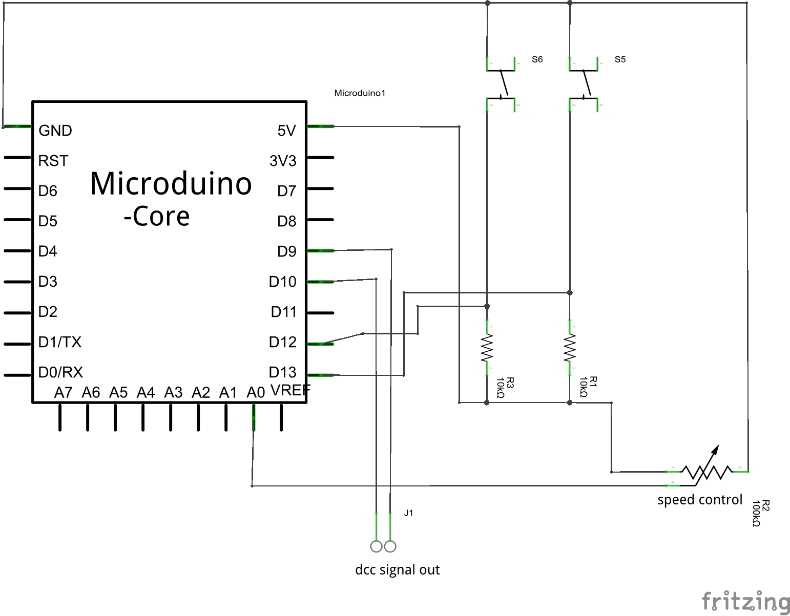
    New Fritzing images using the Microduino, fingers crossed that the CmdrArduino files will work with it. (Updated as incorrectly connected dcc out to ground when it should goto pin 10).


    I need to do more testing of the dcc signal to see if CmdrArduino is running correctly on the microduino.

    Logic Analyser

    The logic analyser works, it supports 4MHz & 2MHz sampling rate. I tried it at 100 kHz sampling rate with the microduino running CmdrArduino, shown below.


    There is limited sampling due to the size of memory on the Uno board, but it is useable, I just need to adjust my triggers.


    What we are seeing is the idle packet for all decoders which is in the format of:

    11111111111111 0 11111111 0 00000000 0 11111111 1 

    As shown on line 90 of the NMRA Specification S-9.2 DCC Communication Standard (pdf document).

    DCC Monitor


    I have put together the dcc monitor and ran it testing the Microduino running CmdrArduino, but with no result, including no idle packets. Looks like dcc monitor cannot handle positive unipolar signal, which is okay as the dcc monitor was designed for trackside which is a bipolar signal. Just means I need to wait until I have my booster before I can test it out.  Correction: CmdrArduino has a differential signal, the example sketch just mentions pin 9, the two pins required are 9 & 10 on Arduino Uno (and microduino).
    Update: dcc monitor will work without booster now that I am using pin 10, instead of ground.


    Between marker 1 (1.45 ms) and 9 (7.23 ms) is the whole dcc idle packet, with both dcc signals shown - pin 9 in purple and pin 10 in blue.

    Saturday 12 July 2014

    DCC Controller

    Currently I am using the railstars CmdrArduino Arduino library (available on github), to generate the dcc signal from my arduino. To ensure that is working correctly I need to verify the signal matches the NMRA specifications for DCC (S-9.1 & S-9.2) using:
    • an Oscilloscope - will be sampling out the basic arduino scopes to see if they are okay for this.
    • a Logic Analyser
    • a dcc monitor/decoder
    Once verified, only then will I connect it to my booster (RAILbooster) and retest it before operating my dcc locomotive with it.

    Shown below is my fritzing project for my test controller. (Updated the diagrams, had dcc out incorrectly connecting to ground when it should be connected to pin 10).


    This controller will be updated once the lcd display and keypad arrive in the mail. 


    dcc monitor/decoder


    I will be using the MynaBay DCC Monitor, there is an alternative library (MRRwA) that The unknown railway has used. Currently I will use the library that comes with the DCC Monitor, as I plan to write some code on my pc to make use of that binary data such as:
    • displaying it in hex
    • verifying that it is valid dcc commands.
    • etc... whatever else comes to mind when I have it operational.


    Oscilloscope


    I will be testing the basic ones out to see if they are useful enough for my purposes. If I do find one that looks okay, I will mention it sometime this weekend or next week.

    The ones I will be looking at are:


    Logic Analyser


    Logic Analyser by gillham and a youtube video of it in action using a frontend called Logic Sniffer.


    Looks like I will start off with the logic analyser and the dcc monitor later today, once done I will start looking into the oscilloscopes.

    Thursday 10 July 2014

    Introduction

    This blog is about my experiences in modelling an n gauge model railway. For a long time I have wanted to model British steam locomotives, and for the last two months that idea has been steadily gaining strength. And then my visit to Aurora Trains moved the idea into action, I saw two British Rail Mark 1 coaches in the crimson and cream livery and knew I must have them. From there I have expanded the coaches up to a rake of six coaches and purchased a Graham Farish n gauge A1 Tornado.


    Video footage of the train in operation, this was taken after the locomotives one hour burn in for each direction.

    The current idea for the layout is a country town terminating station with a freight yard and a spur/branch line to a colliery. This idea will change as I am still researching about country towns, their railways and industry.
    I am already working on an Arduino for the generation of the DCC signal by using the CmdrArduino Arduino library. To continue I need to make some test equipment, such as a DCC monitor and a simple oscilloscope (plenty of Arduino oscilloscope projects), currently waiting on parts to arrive.